Introduction
Legged robots have always been one of the most interesting creations in the robotic industry as they could help us in exploring mysterious lunar caves and other space exploration missions. In fact, legged robots are mobile robots with articulated leg mechanisms that provide locomotion on rough trains. As compared with wheeled robots, they can move on different terrains, although at a slower speed.
Legged robots are often complicated to be made and controlled, as it requires precise control of each leg to maintain its balance. In this project, we are aiming to make a fun and easy-to-build four-legged robot with LEGO®-compatible and an Arduino board (Fig. A).
To do so, we take advantage of interesting mechanical mechanisms that simulate the walking pattern of a real animal, with only one DC gear motor. The result is quite interesting.

In this tutorial, we will make the body and the leg mechanisms of the robot using LEGO®-compatible parts. Then, an off-the-shelf DC gear motor will be connected to the leg mechanism to move the legs.
In the next step, we will need to add a brain to our robot to control its motions. Therefore, we will use Arduino Nano as an intelligent brain (Fig. B). Arduino enables us to expand our Quadruped’s possibilities with various commercially available motors and sensors.

To enhance the performance of the robot, we used an ultrasonic sensor as the eyes of the robot (Fig. C). By using the ultrasonic sensor, the robot can avoid obstacles. Thanks to the open-source nature of the Arduino board that allows such developments.

WWhat materials do you need to build a Quadruped robot?

- TT Gear Motor
- 3D Printed Gear Motor Housing
- 1x Arduino Nano
- 1x Breadboard, Mini Size
- 1x Power Jack, Barrel Type
- 1x Ultrasonic Sensor
- 3D Printed Lego-compatible Coupling
- 1x MOSFET
- 1x M3 x 25 Machine Screw
- 2x M3 x 10 Machine Screw

- Frame, 5x7 module
- Gear, 40-tooth
- Gear, 24-tooth
- Gear, 20-tooth and double bevel
- Bevel gear, 12-tooth
- Gear, 8-tooth
- Beam, 9-module
- Beam, 5-module
- Beam, 3-module
- Angular beam, 3x5 module
-
Axle, 7-module
K2) Axle, 6-module
K3) Axle with stop, 4-module
K4) Axle, 3-module -
Bushing/axle extender, 2-module
-
T-Beam, 3x3 module
-
Angular block 2, 180°
- Connector peg with friction, 3-module
-
Connector peg with friction, 2-module
P2) Connector peg with friction/axle, 2-module
- Beam with cross hole, 2-module
-
Double cross block, 3-module
- Bushing, 1-module
- Axle and pin connector perpendicular
- Connector peg with axle, 2-module
- Bushing, 1/2 module
- Angular block 1, 0°
- Axle connector with axle hole
- Angular block, 6 (90°)
-
Liftarm, 2 x 4 L-Shape Thick
Z2) Universal Joint 3L
Z3) Axle, 2-module
How to use building blocks to assemble the robot?
Let’s start off by assembling the body structure and leg mechanisms of the Quadruped robot. The body structure holds everything together, including the gears, Legs, and electronics. Prepare the LEGO®-compatible pieces according to Fig. E, and follow the step-by-step video tutorial below.
What 3D printed parts do you need?
In order to hold the DC gear motor in place and make a proper connection to the LEGO®-compatible pieces, we have used custom-designed, LEGO®-compatible 3D printed motor housings and shaft couplings (Fig. F). Download and print out the motor housings, couplings. Then prepare the required Lego-compatible parts from Fig. E, and follow the step-by-step mechanical assembly tutorial.

|
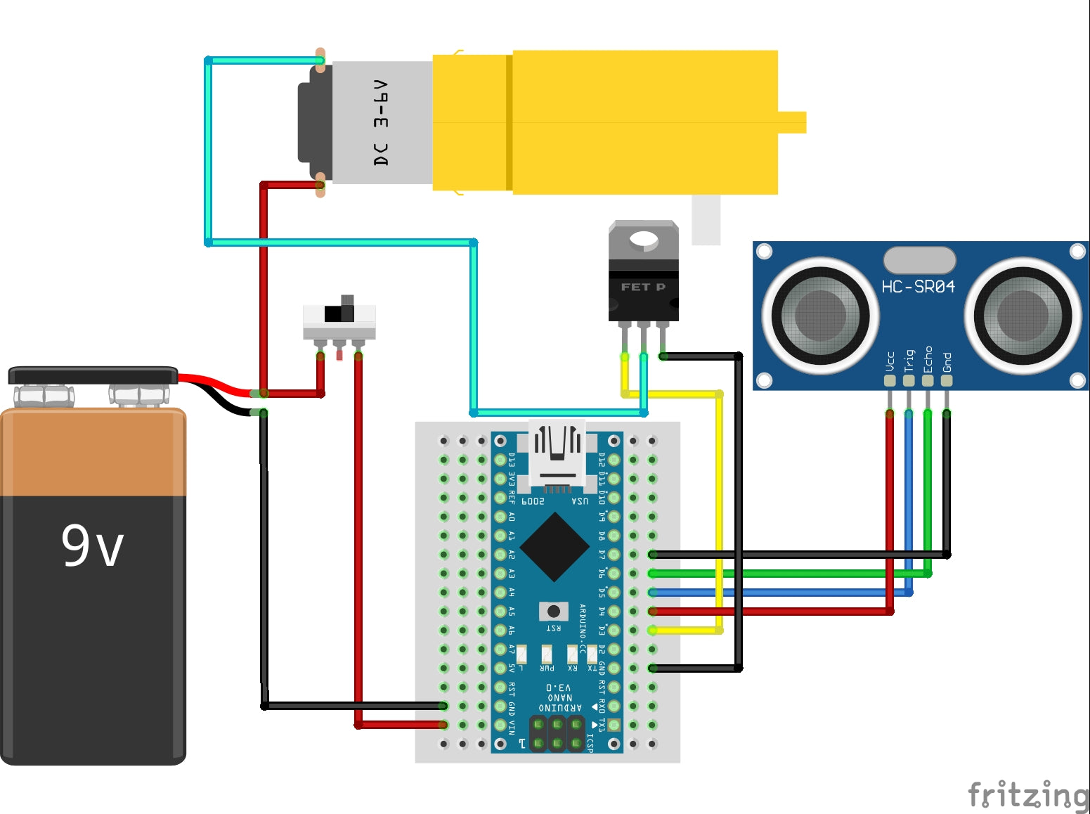
Electronics and wiring
Prepare your screwdriver and soldering iron and carefully follow the video instructions below. Make sure you properly implement the schematic circuit diagram shown in Fig. G so you don't end up toasting your Arduino board and motor driver.
Programming your DIY robot
You can pick up Lego-compatible pieces and let your imagination go limitless. Of course, coding is also the part that you can have lots of fun and be the most creative. You can go to Arduino IDE and write your own code to tell the Quadruped robot to do. But for now, let's start with this code.
  #define VCC 4            // This pin define as Vcc
  #define TRIG 5           // Ultrasonic sensor Trig pin
  #define ECHO 6         // Ultrasonic sensor Echo pin
  #define GND 7           // This pin define as GND
  #define MOTOR 3      // Motor pin

  const int dist = 15;     // Desired distance in cm

  float duration, distance;

  void setup() {
    pinMode(TRIG, OUTPUT);
    pinMode(ECHO, INPUT);

    pinMode(VCC, OUTPUT);
    pinMode(GND, OUTPUT);

    digitalWrite(VCC, HIGH);
    digitalWrite(GND, LOW);
    delay(5000);
  }

  void loop() {
  //  This section is related to Ultrasonics sensor
  /*
    digitalWrite(TRIG, LOW);
    delayMicroseconds(2);
    digitalWrite(TRIG, HIGH);
    delayMicroseconds(10);
    digitalWrite(TRIG, LOW);
    duration = pulseIn(ECHO, HIGH);
    distance = (duration * .0343) / 2;
    if (distance < dist)
      analogWrite(MOTOR, 200);
    else
      analogWrite(MOTOR, 0);
    delay(50);
  */

    analogWrite(MOTOR, 200);
  }