Introduction
Legged robots have always been one of the most interesting creations in the robotic industry as they could help us in exploring mysterious lunar caves and other space exploration missions. In fact, legged robots are mobile robots with articulated leg mechanisms that provide locomotion on rough trains. As compared with wheeled robots, they can move on different terrains, although, at a slower speed.
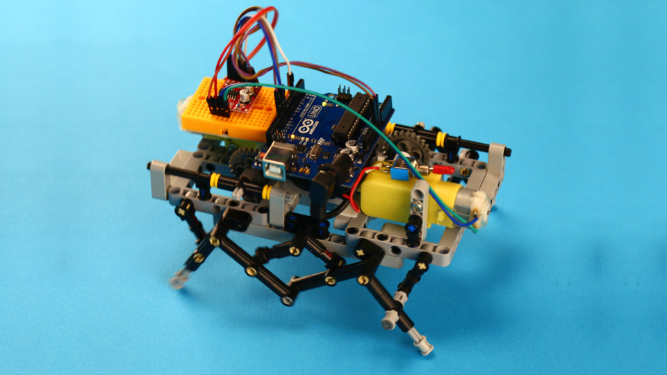
Legged robots are often complicated to make and control, as it requires precise control of each leg to maintain balance. In this project, we are aiming to make a fun and easy-to-build six-legged robot with LEGO®-compatible components and an Arduino board (Fig A).
To do so, we took advantage of interesting mechanical mechanisms that simulate the walking pattern of a six-legged insect, with only one or two DC gear motors. The result came up pretty interesting and pleasing to watch. Don't forget to follow our step-by-step instructions outlined below, and let us know what you think about this subject by commenting below. Your feedback will help us to improve our future work.

In this tutorial, we will show you how to build a robotic hexapod, a six-legged robot, that can walk similar to an insect (Fig B). You will make the body and the leg mechanisms of the robot using LEGO®-compatible parts. Then, commercially available DC gear motors will be connected to the leg mechanism to move the legs.
In the next step, you will need to add a brain to your robot to control its motions. Therefore, we will use Arduino UNO as an intelligent brain (Fig C). Arduino enables you to expand your hexapod’s possibilities with various commercially available motors, sensors, shields, and modules.

The hexapod is made in two different fashions. The first design uses one DC gear motor to move the hexapod back and forth (Fig D), and the second one is driven by two DC gear motors to enhance the maneuverability of the robot (Fig E).

|

|
You can do a variety of different tasks with your hexapod. You can tell the hexapod to track a path by programming your Arduino board. Add a couple of your favorite sensors or even simply control it with a remote joystick, similar to an RC car.
What materials do you need to build a Hexapod robot?

- L298N Mini Motor Driver
- Lego-compatible Coupling
- Mini Toggle Switch
- Bread Boards
- Jumper Wire
- M3 Nut
- M3 Screw
- Battery
- Yellow Gear Motor
- Battery Holder
- Arduino Uno

- Angular block 2, 180°
- Double cross block, 3-module
- Beam, 3-module
- Angular beam, 3x5 module
- Beam, 7-module
- Beam, 13-module
- Frame, 5x7-module
- Angular block 1, 0°
- Axle, 2-module
- Gear, 8-tooth
- Bushing, 1/2 module
- Gear, 24-tooth
- Axle, 6-module
- Axle, 3-module
- Connector peg, 2-module
- Connector peg with friction, 2-module
- Connector peg, 3-module
- Connector peg with axle, 2-module
- Connector peg with friction/axle, 2-module
- Bushing, 1-module
- Axle connector with axle hole
- Beam with crosshole, 2-module
How to use building blocks to assemble the robot?
First, let’s assemble our hexapod’s body and leg mechanisms. Prepare the LEGO®-compatible pieces according to Fig. F, and follow the step-by-step video tutorial below.
What 3D printed parts do you need?
LEGO®-compatible components only match with LEGO®-compatible gear motors. In order to connect the shafts of the commercially available gear motors to LEGO®-compatible components, we need to 3D print a coupling that makes the motor shaft compatible with its LEGO®-compatible counterpart. This is called LEGO®-compatible motor shaft coupling (Fig. G). So, go ahead and download the Lego-compatible Motor Shaft Coupling 3D-print file. Then, find a 3D printer nearby or use yours.

|

|

|
Electronics and wiring
Grab your screwdriver, warm up your soldering iron, and follow the video instruction below. Don’t forget to carefully implement the circuit diagram, so you don’t end up toasting your precious Arduino board.

Programming your DIY robot
And last but not least, is the intelligent brain of your hexapod. Although you can do more development with the mechanical and the electrical parts of your hexapod. Programming is indeed the part that you can be most creative at. For now, let’s start with this code.
    #define M1 11
#define M12 10
#define M2 9
#define M22 5


void setup() {
  // Initialize Arduino pins to outputs
  pinMode(M1, OUTPUT);
  pinMode(M12, OUTPUT);
  pinMode(M2, OUTPUT);
  pinMode(M22, OUTPUT);
}

void loop() {
  goForward();
  delay(3000);

  goBackward();
  delay(3000);

  turnLeft();
  delay(3000);

  turnRight();
  delay(3000);
}

// Configures driver motor pins to go forward.
void goForward() {
  digitalWrite(M1, LOW);
  analogWrite(M12, 200);
  analogWrite(M2, 200);
  digitalWrite(M22, LOW);
}

// Configures driver motor pins to go backward.
void goBackward() {
  digitalWrite(M12, LOW);
  analogWrite(M1, 200);
  analogWrite(M22, 200);
  digitalWrite(M2, LOW);
}

// Configures driver motor pins to turn left.
void turnLeft() {
  digitalWrite(M12, LOW);
  analogWrite(M1, 200);
  analogWrite(M2, 200);
  digitalWrite(M22, LOW);
}

// Configures driver motor pins to turn right.
void turnRight() {
  digitalWrite(M1, LOW);
  analogWrite(M12, 200);
  analogWrite(M22, 200);
  digitalWrite(M2, LOW);
}
